

KYN28A-12 Armored Removable Mediun Voltage Switchgear (Bus Coupler Cabinet)
Request a Quote
Enter the quantity you need and add to your quote list for pricing inquiries.
Product Details


KYN28A-12 Metal-Clad Withdrawable Medium Voltage Switchgear (Bus Coupler Cabinet)
1. Product Overview
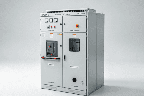
The KYN28A-12 bus coupler cabinet, also known as bus tie cabinet, is a special type of 12kV indoor armored withdrawable central switchgear, exclusively used for connecting two independent sections of main busbars in a double-busbar or double-incoming power distribution system. It is arranged between two groups of high-voltage cabinets to realize interconnection, power transfer and mutual backup of two power sources.
Different from incoming cabinets and feeder cabinets, this cabinet has no external incoming or outgoing cable loads. Its core task is to control the connection and disconnection between Section I main busbar and Section II main busbar. It adopts the same four-compartment fully isolated arc-proof metal partition structure as the whole KYN28A-12 series, with IP4X protection grade and complete five-prevention mechanical and electrical interlock system. Equipped with VS1 vacuum circuit breaker trolley as the core switching component, it is widely applied in large industrial plants, data centers, commercial complex substations, photovoltaic power stations and overseas dual-power supply projects requiring high power supply reliability.
2. Main Internal Equipment Configuration
Primary Circuit Core Devices
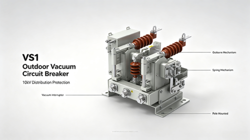
VS1 Vacuum Circuit Breaker Trolley for Bus Coupling
The key switching component installed in the middle trolley compartment. Its upper static contacts connect to Section I busbar, and the other set of static contacts link to Section II busbar. It controls the connection of two bus sections, realizing power mutual transfer when one incoming power supply fails. It has three working positions: working position, test position and isolation position, supporting manual and electric closing & opening operation.
Coupling Current Transformer CT
Series-mounted on both sides of the bus tie breaker, converting high primary current into standard secondary current signals. The signals are transmitted to comprehensive protection relays for overcurrent, short-circuit and interlocking protection judgment of the two bus sections.
Dual-section Main Busbar & Branch Copper Busbars
Two groups of insulated TMY copper busbars run through the cabinet separately, corresponding to Busbar Section I and Busbar Section II. They form the conductive channel for power exchange between two power supply sections.
Earthing Switch
Installed inside the lower cable compartment of the cabinet, mechanically interlocked with the bus tie breaker trolley. After the trolley is withdrawn to the isolation position, the earthing switch can be closed to release residual high voltage on busbars for safe maintenance.
High-Voltage Live Display Sensors
Inductive sensors are installed on both bus sections to detect the electrified state of two groups of busbars simultaneously, with warning indicators on the cabinet door to remind operators of dual high-voltage risks.
Secondary Control & Interlock Protection Components
Dual-power Interlock Microcomputer Protection Relay
The core secondary control unit, specially designed for bus tie protection. It monitors voltage and current of two bus sections, realizes interlocking logic of two incoming cabinets and the bus tie cabinet, and executes protection functions such as busbar short-circuit protection, overcurrent protection and loss-of-power automatic switching.
Local Operation Control Panel
Concentrated in the upper secondary instrument compartment, including closing/opening buttons, breaker status indicator lights, busbar live indicators and fault sound-light alarm buzzer, supporting on-site manual operation and status viewing.
Secondary Terminal Block & RS485 Communication Module
Centralized wiring for all sampling signals and interlock control loops. The communication module uploads bus tie breaker status, two-section bus voltage, current and fault records to the intelligent power monitoring SCADA system for remote centralized management.
Electrical Interlock Auxiliary Contacts
Hard-wired interlock signals linked with two incoming cabinet breakers, forming strict three-interlock logic: only one of the two incoming breakers and bus tie breaker can be closed at the same time to avoid parallel short-circuit of two different power sources.
Cabinet Safety Structural Parts
Four independent closed compartments: bus compartment, bus tie breaker trolley compartment, cable compartment and secondary instrument compartment, separated by thick arc-resistant metal plates to block the spread of high-temperature fault arcs.
Top pressure relief channel: automatically discharge high-temperature and high-pressure gas generated by busbar short-circuit faults to prevent cabinet deformation or explosion.
Full set of five-prevention mechanical interlock devices to eliminate all dangerous misoperation behaviors during operation and maintenance.
3. Working Principle
3.1 Dual Busbar Power Interconnection Principle
In a double-incoming single-section bus system, two independent 10kV power sources supply Busbar Section I and Busbar Section II respectively. The bus tie cabinet’s vacuum breaker trolley acts as the bridge between the two bus sections.
When both incoming power supplies operate normally, the bus tie breaker remains open, and two bus sections run independently to share loads separately.
When one incoming power supply fails or loses voltage, the interlock protection relay judges the power loss signal, sends a trip command to the faulty incoming breaker, then sends a closing command to the bus tie breaker after a short delay. The two bus sections are connected, and all loads are supplied by the other intact power source, realizing uninterrupted power transfer.
The dual-group copper busbars inside the cabinet transmit power between the two sections after the bus tie breaker is closed, completing the backup power supply switching loop.
3.2 Bus Tie Fault Protection Principle
The CTs on both sides of the vacuum breaker collect the cross current between two bus sections and transmit signals to the bus tie comprehensive protection relay:
Busbar short-circuit protection: When phase-to-phase short circuit occurs on any bus section, the protection device instantly trips the bus tie breaker and corresponding incoming breaker to isolate the fault range and prevent fault diffusion to the other bus section.
Overcurrent protection: When the total load exceeds the rated carrying capacity of the single remaining power source after power switching, delayed tripping is executed to avoid overload damage of the standby power supply.
Reverse power protection: Prevent reverse power transmission to the grid side when the generator load is connected to the distribution system.
3.3 Three-Party Electrical Interlock Working Principle
The most critical core logic of the bus coupler cabinet: interlock linkage with two incoming cabinet breakers.
If Incoming Breaker 1 and Incoming Breaker 2 are both closed, the bus tie breaker will be locked and cannot be closed, avoiding parallel connection of two different power sources to cause severe short-circuit accidents.
When any one incoming breaker trips due to power loss or fault, the interlock circuit releases the locking signal of the bus tie breaker, allowing automatic closing of the bus tie to switch all loads to the other power supply.
When the bus tie breaker is manually closed for maintenance test, the two incoming breakers will be locked to prevent simultaneous power supply to two bus sections.
3.4 Five-Prevention Interlock & Maintenance Safety Principle
Complete mechanical interlock devices eliminate misoperation risks:
The bus tie breaker can only be closed when the trolley is locked at working or test position; closing is forbidden during trolley pushing or pulling.
The earthing switch can only be closed after the trolley is withdrawn to isolation position and the breaker is fully opened, to forbid live earthing.
The cabinet front door cannot be opened when the trolley is in working position with dual live busbars inside.
The trolley cannot be pushed into the working position if the earthing switch is closed, avoiding grounding short-circuit of dual busbars.
Before busbar maintenance, operators open the bus tie breaker, shake out the trolley, close the earthing switch to discharge residual high voltage on both bus sections, forming a zero-voltage safe maintenance environment.
3.5 Cabinet Integral Grounding Safety Principle
The cabinet metal shell, all arc-proof partitions, CT supports and earthing switch are reliably connected to the station’s overall grounding grid via flat steel strips. If insulation damage causes cabinet leakage, leakage current will be rapidly guided into underground earth to prevent electric shock accidents for operation and maintenance personnel.
4. Core Functions of KYN28A-12 Bus Coupler Cabinet
Dual Busbar Connection & Power Mutual Backup
Realize electrical connection between two groups of main busbars, complete automatic load transfer when one power supply fails, greatly improve the reliability of power supply for important loads such as data centers and medical buildings.
Strict Three-Way Interlock Protection
Match interlock logic with two incoming cabinets to completely avoid parallel short-circuit of two independent power sources, eliminating major grid hidden dangers.
Busbar Fault Isolation & Cross-current Protection
Quickly cut off the connection between two bus sections when busbar short-circuit or overload occurs, limit the fault scope to a single bus section and reduce power outage range.
Manual/Automatic Dual-mode Switching Control
Support automatic power switching under fault conditions, as well as manual closing/opening for scheduled power transfer and maintenance debugging.
Real-time Dual Bus Operating Data Monitoring & Remote Upload
Collect voltage, current and switch status of two bus sections, upload data to remote monitoring system via communication module, realize unattended intelligent management of dual-power distribution rooms.
Full Arc Suppression & Safe Maintenance Guarantee
Independent arc-proof compartments and top pressure relief structure reduce safety hazards caused by busbar faults; matched earthing switch and five-prevention interlock ensure safe inspection of dual busbars.
5. Main Technical Parameters
Rated voltage: 12kV
Rated frequency: 50Hz / 60Hz (customizable for global overseas markets)
Main busbar rated current: 1250A, 1600A, 2000A, 2500A, 3150A
Rated short-time withstand current: 20kA, 25kA, 31.5kA
Cabinet protection grade: IP4X
Operating ambient temperature: -10℃ ~ +40℃
Applicable environment: Indoor dry medium-voltage distribution room with dual-power supply demand
6. Foreign Trade Promotion Advantages (Suitable for Official Website Display)
Standard KYN28A-12 modular design, perfectly matched with incoming cabinets, PT cabinets and feeder cabinets to form a complete double-bus distribution system;
Unique three-way interlock protection logic, fully comply with international dual-power distribution safety standards, recognized by overseas power grid clients;
Withdrawable bus tie vacuum breaker trolley, convenient for replacement and maintenance without cutting off two bus sections at the same time, low maintenance cost;
Integrated dual-bus live monitoring function, simultaneously detect the electrified state of two groups of busbars with high safety warning performance;
Support 50Hz/60Hz dual frequency customization, applicable to high-reliability power supply projects in Southeast Asia, Middle East, Africa and Europe;
Intelligent automatic switching function, reduce manual operation intervention, meet the construction requirements of modern smart unattended substations;
Complete arc isolation and pressure relief safety structure, effectively resist severe busbar short-circuit faults, suitable for large industrial and commercial heavy-load projects.